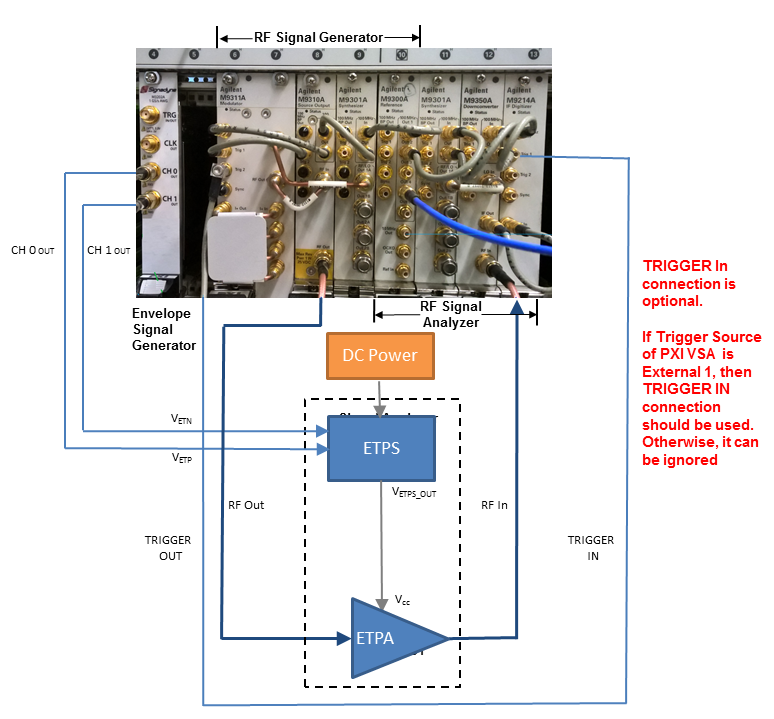
The following figure shows the instrument connection of envelope tracking measurement. The figure shows the measurement setup when M320xA PXI AWG is used as envelope signal generator.
Figure 1. Envelope tracking measurement setup when M320xA PXI AWG is used as envelope signal generator
In the system connection diagram above, the dark blue lines are for RF connection; the light blue lines are for reference, trigger, and envelope signal connection; the black lines are for instrument control connection with LAN or GPIB. In envelope tracking test, timing alignment is required between the ETPA Vcc input and the RF input signal
Follow the procedure below to set up the measurement system:
Software Installation of M320xA AWG
Ensure that you have Microsoft .NET Framework 4.5 or later installed on the Windows operating system (PC or Windows-based instrument) that is to receive the Signal Studio software download.
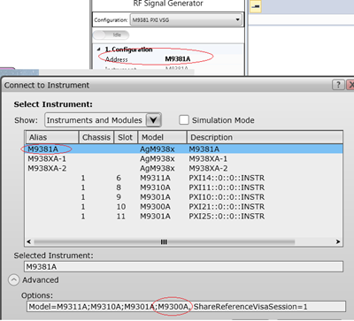
In case you select the M9381 PXIe VSG or M9391 PXIe VSA, it is necessary that one of them should at least contain M9300A Reference module:
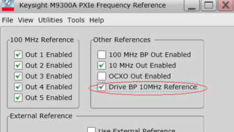
In case none of them contains M9300A module, select the Drive BP 10MHz Reference check box from the M9300A SFP to use the 10 MHz reference signal on the backplane for the alignment of the RF signal and the envelope signal.
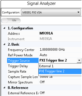
The following two options are available in the N7614C software to select the source of the trigger signal for PXIe VSA:
External means that the trigger signal originates at the Trig 1 on the M9214A front panel.
PXI Trigger line 2 means that the trigger signal originates from PXI backplane line 2. PXI Trigger Line 2 is the preferred Trigger Source and is the default value.
In case there is only one Signadyne AWG module in the PXI chassis, no need to specify the address and slot number of the AWG. N7614C software detects it automatically.
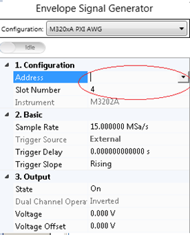
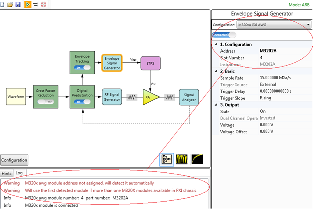
However, in case there are more than one Signadyne AWG modules in a PXI chassis, specify the exact address and slot number of the AWG in the N7614C software.
Follow the steps below to install the M320xA AWG software:
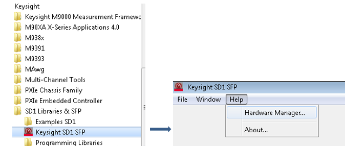
Keysight recommends that you should use the latest Keysight SD1 package for the initialization of M9320xA AWG driver. The old Signadyne driver for M320xA AWG is outdated but still can be used to initialize the M320xA AWG. However, while connecting M320xA AWG to the latest version of N7614 software, Keysight SD1 driver is called first. In case the driver initialization fails or Keysight SD1 driver is not found, then the old Signadyne driver will be called to initialize the AWG.
The table below shows the supported instruments for envelope tracking measurement. For details about the options required for each instrument model, see System Requirements.
|
Instrument Type |
Instrument Model Supported |
|---|---|
|
RF Signal Generator |
M938xA |
|
Envelope Signal Generator |
M320xA Arbitrary Waveform Generator |
|
Signal Analyzer |
M939xA |
To set up the measurement system, follow the steps below:
Connect the M320xA Envelope Signal Generator output to the ETPS. Connect the CH 0 OUT and CH 1 OUT ports of the Envelope Signal Generator to the VETP and VETN ports of the ETPS respectively and connect the VETPS_OUT port of the ETPS to the Vcc of the ETPA.
This is to synchronize the RF Signal Generator and Signal Analyzer in time domain.
Connect the Trig 2 port on the front panel of the M9311A Modulator of the RF Signal Generator to the Trig 1 port on the front panel of the M9214A Digitizer of the Signal Analyzer. Alternatively, use the trigger signal from PXI backplane line 2, PXI Trigger Line 2.
Connect the RF OUTPUT port of the RF Signal Generator to the input of the PA and connect the output of the PA to the RF INPUT port of the Signal Analyzer.